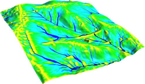
A catchment boundary defines the area draining to a selected outlet and underpins area, runoff and discharge calculations. Automatic delineation may misrepresent roads, culverts, pipes or survey gaps. Owners should know the outlet and source terrain. Engineers compare automated results with topography and real drainage connections before using them as inputs.
Preparing the terrain data
Check raster coordinates, cell size, height units, vertical datum and missing data. Use a projection appropriate for area and length; degrees are not metres. Surface models containing buildings or vegetation differ from bare-earth terrain. Check elevation compatibility at raster seams and include enough upstream coverage to avoid truncating the drainage area.
Depressions and hydrological conditioning
Depressions may be real storage or data artefacts. Filling or breaching can support flow-direction processing, but indiscriminate filling removes genuine storage. Record changes and represent culvert connections where roads incorrectly block drainage. Preserve original terrain; a conditioned drainage surface is not automatically the physical terrain for hydraulic flooding calculations.
Flow direction, accumulation and streams
Flow direction identifies downstream neighbours; accumulation represents contributing cells or area. A threshold extracts streams. Too small a threshold creates excessive branches; too large omits tributaries. Compare the network with imagery, maps and field knowledge, documenting algorithm and threshold. Direction uncertainty in flat or coarse terrain can exceed what a neat boundary line suggests.
Placing the outlet correctly
Tie the outlet to a bridge, culvert or assessed section. A point on the wrong cell or branch can create a different catchment. If snapping to accumulation is used, check distance and the selected cell; it may select a neighbouring stream. A bridge upstream of a confluence and a section downstream need not share drainage area. Document coordinates and section context.
Independent boundary and area checks
Compare the boundary with ridges, known streams and adjacent subcatchments. Calculate area in appropriate units and check km² conversion. Represent urban drainage crossing natural divides. Test sensitivity to outlet or terrain resolution where useful. Deliver outlet, boundary, streams, source, processing and area table together. Successful processing does not establish field validity.
Traceability and reporting scope
For traceable hydrological calculations, record the source, observation period, units and missing-data treatment of the rainfall or streamflow series. Keep the catchment boundary, area calculation, land use, soil information and parameters of the selected method in the same data package. Calculation sheets should show inputs and unit conversions as well as the answer. Another engineer opening the files should be able to understand where each datum came from and the step in which it was used.
It is helpful for the project owner to share the location, study boundary and available mapping at the outset. Missing information does not automatically justify completing the calculation with a single assumption: surveys, alternative data or a narrower scope may be needed. Explain why the selected method suits the catchment and study purpose. The report should present uncertainties and checking scenarios alongside the central assumptions. Hydrological discharge and hydraulic water level are different outputs; where needed, a separate hydraulic model evaluates the effect of that discharge on structures or parcel elevations.
Sources and related articles
Let's discuss your project's data requirements and reporting scope.
Request a project quote